THE PROJECT NOTEBOOK

Notes from
inside the system.

A few questions.
A lot of looking closely.

SMART MUSHROOM HUB

A small space. Plenty of questions.
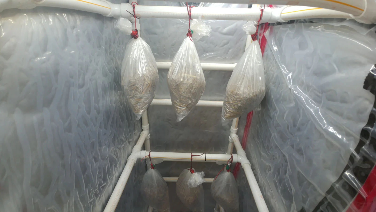
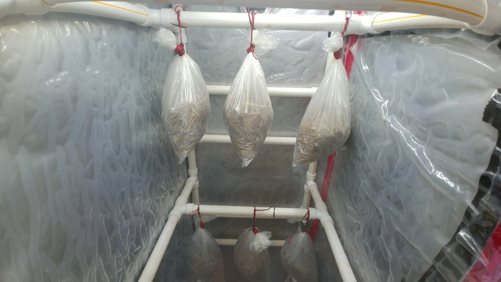
Controlled-camera photograph of hanging cultivation bags inside the tent.
1

The hanging bags contain the growing substrate. This photograph records one moment; it does not establish a growth rate.

Inside the tent · 19 August 2026

Actual experiment photograph

Look closely, then look again.

CLICK THE PHOTO TO LOOK CLOSER01
01 / THE IDEA

Why create a controlled habitat?

I have always been fond of mushrooms since the day I learnt about them. I was fascinated by how distinct they are from the plant kingdom: how they consume the substrate provided to them, and how diverse and colourful they are. After a couple of at-home experiments to grow my own mushrooms, I thought: how about I create an automated system that gives my mushrooms the required habitat to grow efficiently?
Two questions to carry forward

  1. How do conditions inside the tent compare with the surrounding room?
  2. How do controlled conditions increase the yield of the mushrooms?
02
SMART MUSHROOM HUB

Follow the wire back to its purpose.

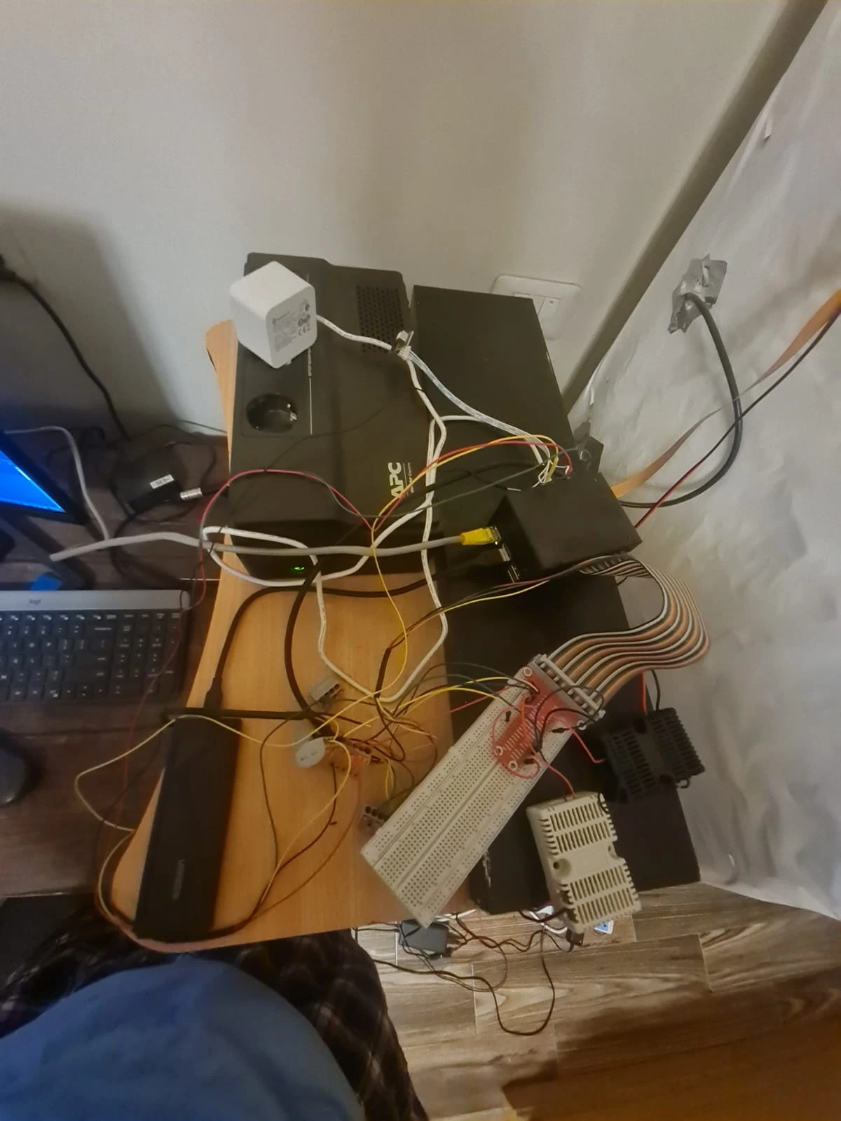
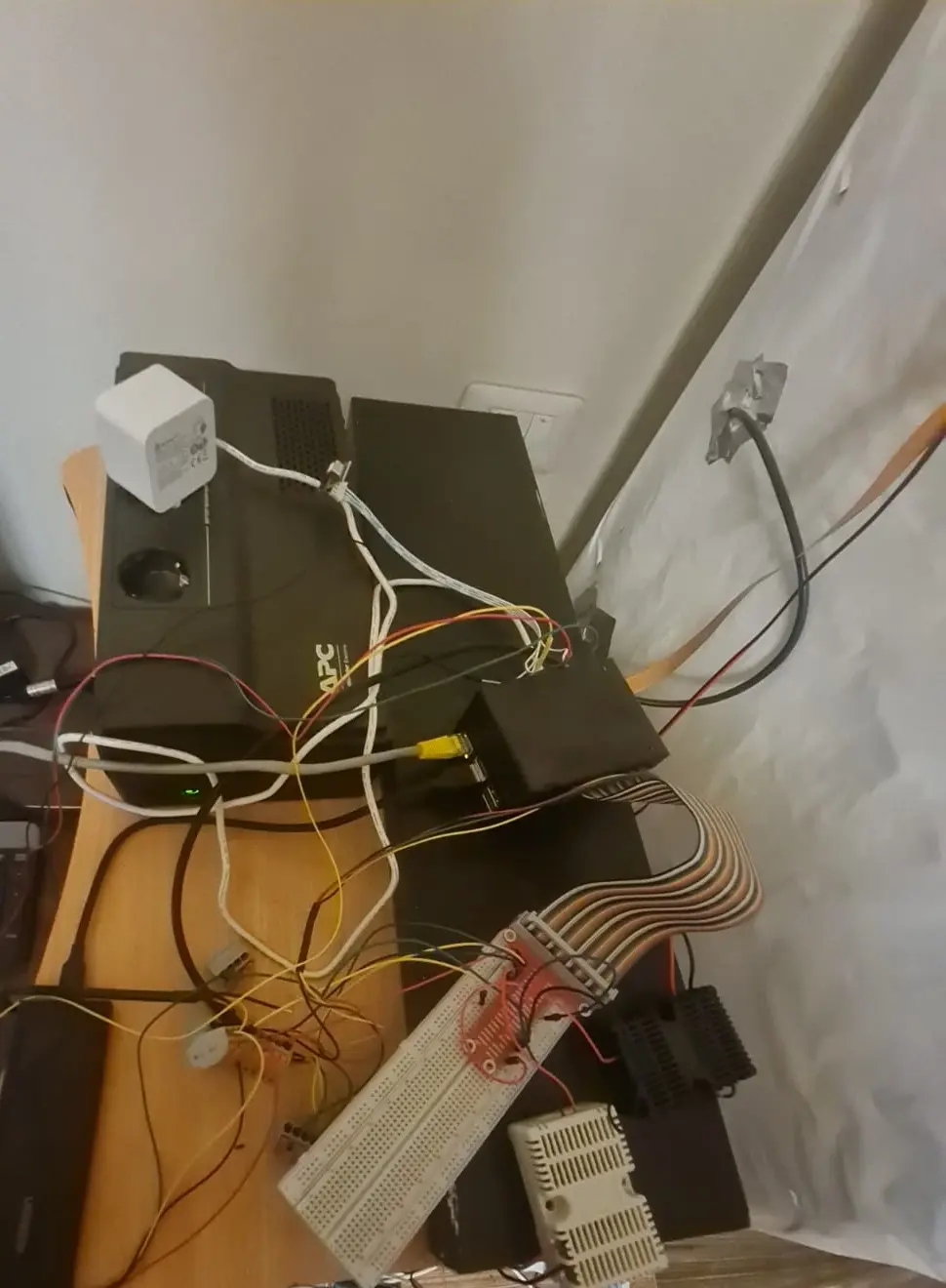
Cropped workbench photograph showing the UPS, wiring, breakout and computing hardware.
The workbench
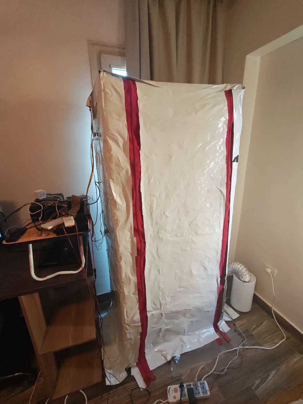
The enclosed mushroom tent beside its workbench and humidifier.
The entire setup

Supplied setup photographs

The messy part belongs in the notebook, too.

CLICK THE PHOTO TO LOOK CLOSER03
02 / THE BUILD

The hardware, at a glance.

Hardware and materials in the mushroom habitat
FrameThe documented frame is approximately 185 cm high × 82 cm wide × 55 cm deep, built from 1.5-inch PVC pipe with diagonal reinforcement. Plastic covering, zippered access and acrylic camera windows enclose the growing space.
ComputingRaspberry Pi 5, 16 GB RAM; Raspberry Pi AI HAT 2 with a Hailo-10H accelerator.
StorageSSD storage in a UGREEN enclosure.
EnvironmentTwo SHT31 temperature/humidity sensors and two SCD41 CO₂ sensors: one of each for the tent and the ambient room.
ImagingTwo Raspberry Pi Camera Module 3 Wide cameras.
VentilationThermalright TL-C12C-S V3 120 mm PWM fan.
MoistureXiaomi Humidifier 2, connected by a flexible duct.
Light1 metre of IP67 LED lighting.
PowerSchneider BVS 800 VA UPS.
04
SMART MUSHROOM HUB
PICK A LAYER TO READ ITS NOTE05
03 / THE SOFTWARE

THE SOFTWARE

Choose a layer

  1. 01Sensors
  2. 02Python service
  3. 03MQTT
  4. 04Database
  5. 05Phases
  6. 06Controller
  7. 07Actuators
  8. 08Lighting
  9. 09Camera
  10. 10Grafana

THE SOFTWARE / 01 OF 10

Sensor Data Acquisition

What it does

Collects environmental data from inside the Mushroom Hub and from the surrounding room.

How it works

Two sensor pairs are used: SHT31 for temperature/humidity and SCD41 for CO₂. They communicate with the Raspberry Pi over I²C. SHT31 addresses can be changed, but SCD41 sensors share a fixed address, so the pairs are separated across different I²C buses. WAGO connectors are used to organize/distribute the wiring.

Output / Destination

Temperature, humidity and CO₂ readings are passed to the Python sensor service.

THE SOFTWARE / 02 OF 10

Python Sensor Service

What it does

Converts raw sensor communication into usable software data.

How it works

A Python service periodically reads each sensor over I²C, identifies its location/device, packages the measurements and prepares them for the rest of the system.

Output / Destination

Publishes sensor readings to MQTT topics.

THE SOFTWARE / 03 OF 10

MQTT Messaging Layer

What it does

Acts as the communication layer connecting the different services.

How it works

Mosquitto runs as the MQTT broker. Services publish messages to topics, while any interested service can independently subscribe to those topics. This keeps the architecture loosely coupled.

Output / Destination

Messages can simultaneously reach the database writer, environment controller, actuators and other services.

THE SOFTWARE / 04 OF 10

Database Ingestion

What it does

Creates a historical record of everything happening in the Mushroom Hub.

How it works

A database-writer service subscribes to MQTT messages and writes them into TimescaleDB, which is built on PostgreSQL and optimized for time-series data.

Output / Destination

Stores sensor readings, timestamps, device/location information, controller decisions, actuator events, lighting events and camera metadata.

THE SOFTWARE / 05 OF 10

Experiment / Phase Configuration

What it does

Defines how the Mushroom Hub should behave during different growth stages.

How it works

Configuration tables in the database contain environmental targets and operating rules for phases such as incubation and fruiting. The active phase is changed manually in the database.

Output / Destination

Provides rules and target values to the controllers and scheduled services.

THE SOFTWARE / 06 OF 10

Environment Controller

What it does

Acts as the decision-making layer for environmental control.

How it works

Subscribes to live MQTT sensor readings and compares them against the rules for the currently active growth phase. For example, low humidity can trigger a humidifier decision, while high temperature or CO₂ can trigger ventilation.

Output / Destination

Publishes actuator commands through MQTT and records controller decisions in the database.

THE SOFTWARE / 07 OF 10

Actuator Layer

What it does

Converts software decisions into physical actions.

How it works

Actuator services subscribe to MQTT command topics. The controller decides what should happen, while the actuator layer handles how the physical device is controlled.

Output / Destination

Controls devices such as the exhaust fan and humidifier and records actuator events in the database.

THE SOFTWARE / 08 OF 10

Lighting Automation

What it does

Controls lighting according to the active growth phase and camera schedule.

How it works

During incubation, LEDs remain off except briefly when images are being captured. During fruiting, the LEDs remain on according to the configured fruiting setup.

Output / Destination

Controls the LED lighting and records its activity.

THE SOFTWARE / 09 OF 10

Camera Automation

What it does

Creates a consistent visual history of mushroom growth.

How it works

During incubation, images are captured approximately every 6 hours. During fruiting, captures occur approximately every 1 hour. Before each image, the exhaust fan runs briefly to remove excess humidifier mist that would otherwise make the camera image appear white.

Output / Destination

Images are saved with timestamps/experiment metadata and can later be combined into timelapses.

THE SOFTWARE / 10 OF 10

Grafana Visualization

What it does

Provides a visual interface for monitoring and analysing the experiment.

How it works

Grafana queries the historical data stored in TimescaleDB and presents it through dashboards and time-series graphs.

Output / Destination

Displays trends such as temperature, humidity, CO₂ and system/device activity over time.

06
SMART MUSHROOM HUB

A quiet-looking bag is still worth watching.

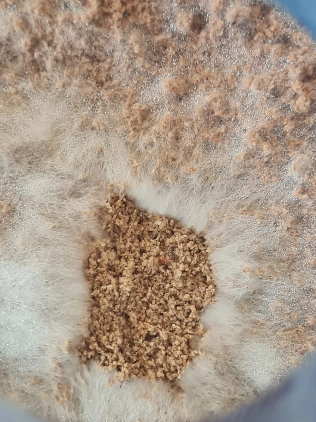
Actual controlled-camera still of the hanging bags during incubation on 27 August 2026.
1

Surface appearance reveals only part of colonization. The date identifies this still; it does not imply that pinning or fruiting had begun.

An incubation observation ·

Actual experiment photograph

Observe first. Interpret carefully.

CLICK THE PHOTO TO LOOK CLOSER07
04 / GROWING NOTES

Learning to notice slowly

Growth has its own pace.

Incubation → pinning → fruiting → harvest. These are conceptual stages of cultivation, not a claim that this run reached every stage.

During incubation, mycelium spreads through the substrate. Later, small mushroom initials may appear before developing into recognizable clusters.

Keep two records side by side

Photographs preserve visible changes. Grafana holds the environmental measurements and history. Neither record can explain everything on its own.

The documented incubation schedule calls for a full-resolution still every six hours from each camera. Selected captures from 19 August, 27 August, and 4 September 2026 are published on the site.

View the photographs and prepared timelapse →

08
SMART MUSHROOM HUB

Seeing is not the same as understanding.

Unannotated experiment photograph captured on 4 September 2026, with no model detections added.
1

This is an original observation image, not a detection example. Genuine model outputs can be added here when available.

A camera still, before any interpretation · 4 September 2026

Actual photograph · not a YOLO prediction

A prediction needs its own evidence.

CLICK THE PHOTO TO LOOK CLOSER09
05 / VISION LAB

From an image to a question

What does the camera see?

The computer-vision work asks whether a model can recognize mushrooms in images of the growing space.

Trained, with more work ahead

A YOLOv8s model has been trained with mushroom as its primary class. The project brief reports approximately 0.9443 mAP50 in model evaluation.

That result does not establish reliability in the deployed tent. Edge inference using the Pi AI HAT 2 and Hailo-10H is planned; the complete camera-to-inference pipeline is not documented as deployed.

Still to investigate

How do lighting, overlapping clusters, and changes in viewpoint affect predictions? Counting and growth tracking need their own evaluation.

10
SMART MUSHROOM HUB

Every little part has a story.

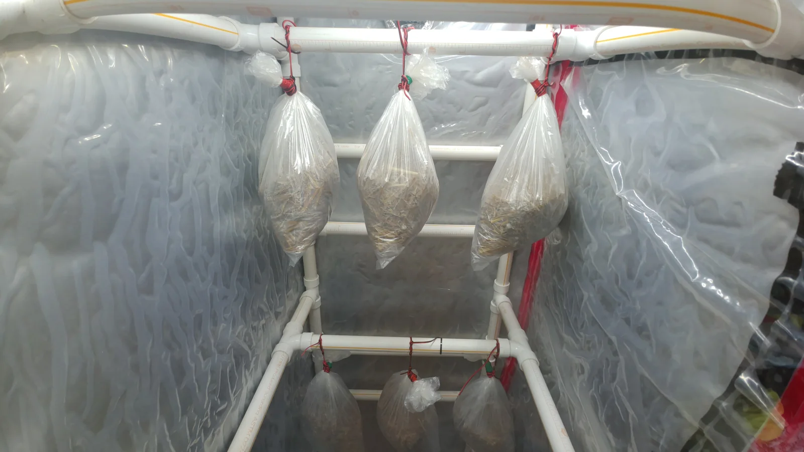
Cultivation bags hanging from the PVC supports inside the covered tent.
1

The frame, covering and hanging bags come together in the growing space. The side tabs organize the materials and systems behind the build.

The growing space, brought together · 19 August 2026

Actual experiment photograph

Follow the coloured tabs, from the frame to cultivation.

CLICK THE PHOTO TO LOOK CLOSER11
06 / THE JOURNEY

THE JOURNEY

Choose a build step

  1. 01PVC Pipes
  2. 02Transparent Plastic
  3. 03Raspberry Pi
  4. 04Fan
  5. 05Humidifier
  6. 06LED
  7. 07White Car Vinyl
  8. 08Sensors
  9. 09UPS
  10. 10MOSFETs and Wiring
  11. 11Mushroom Cultivation

THE JOURNEY / 01 OF 11

PVC Pipes

The shape of the growing space.

Unfortunately, I couldn’t find a Martha tent locally in Egypt, so I had to build most of the setup myself. I began by looking for a material that would be easy to assemble and resistant to moisture. PVC pipes seemed like the best choice.

First, I designed the frame using Crafty Amigo and calculated the number and lengths of PVC pipes I would need. That process led to the first version of the structure.

I then bought the pipes, cut them one piece at a time, and washed every piece in the bathtub before assembly. Once the frame was standing, it felt a little too wobbly because some of my cuts were not perfectly even. To make it stronger and more rigid, I added an X-shaped diagonal support.

THE JOURNEY / 02 OF 11

Transparent Plastic

A boundary you can see through.

To enclose the tent, I needed to cover the PVC frame with transparent plastic. At first, I considered using UV-treated greenhouse plastic and contacted several factories to find it. However, they only sold it in large rolls of around 50 metres, which was far more than I needed. Since the tent would remain indoors and would not be exposed to direct sunlight, I decided that the additional UV protection was unnecessary and settled on ordinary transparent plastic instead.

I then measured the frame to calculate how much plastic I would need, covered the entire structure, and sealed the seams using moisture-resistant tape.

THE JOURNEY / 03 OF 11

Raspberry Pi

A small computer, many responsibilities.

I bought the Raspberry Pi 5 with 16 GB of RAM. This was more than the system strictly required, but I preferred to leave myself extra headroom rather than risk being limited later. It also gives me the flexibility to reuse the Pi for more complex projects in the future.

For computer-vision inference, I added a Raspberry Pi AI HAT+ 2. Its Hailo-10H accelerator allows the vision models to run locally without relying entirely on the Raspberry Pi’s CPU.

Because microSD cards are not ideal for sustained, write-heavy workloads, I decided to use the SSD from my old laptop as the system’s primary storage. I placed it inside a UGREEN SSD enclosure and connected it to the Raspberry Pi.

I couldn’t use a standard Raspberry Pi case because it did not have enough space for the additional HAT. Instead, I chose a KSSB-style case with enough clearance to accommodate both the Raspberry Pi and the accelerator.

THE JOURNEY / 04 OF 11

Fan

Make room for fresh air.

I chose a 12 V Thermalright fan to manage ventilation inside the tent. It replaces stale air with fresh air and helps prevent CO₂ from accumulating around the mushrooms. My intended range is approximately 400-600 ppm, although the final control thresholds may need adjustment during cultivation.

The fan is installed at the bottom-right side of the tent, while an air vent is positioned on the upper-left side. Placing them on opposite sides encourages air to move diagonally through the growing space instead of circulating around a single area.

THE JOURNEY / 05 OF 11

Humidifier

Bring moisture into the habitat.

I chose a Xiaomi Smart Humidifier 2 to maintain the high humidity required during fruiting. Its smart-home support also makes it easier to integrate the humidifier into the automated control system. The humidifier stands beside the tent, where a flexible duct carries its mist into the growing space.

THE JOURNEY / 06 OF 11

LED

Light inside the growing space.

Mushrooms do not use light for photosynthesis, but light still acts as an important environmental cue during fruiting. I added a one-metre, IP67-rated LED strip to provide consistent illumination while better tolerating the tent’s humid conditions.

The LED can remain off during colonization and switch on when the mushrooms enter the fruiting stage. It is mounted near the top of the tent and connected to its own MOSFET-controlled 24 V circuit.

THE JOURNEY / 07 OF 11

White Car Vinyl

A place for the finishing details.

The room containing the tent is quite dark, so the LED strip alone did not distribute light evenly throughout the growing space. I applied white automotive vinyl to selected parts of the tent covering to create a brighter interior surface and reflect more of the available light back toward the mushrooms.

This also gives me clearer separation between cultivation phases: the LED can remain off during colonization, then provide a brighter and more evenly lit environment during fruiting.

THE JOURNEY / 08 OF 11

Sensors

Listen to the surrounding conditions.

I use two types of environmental sensor. The SHT31 measures temperature and relative humidity, while the SCD41 measures carbon-dioxide concentration.

There are four sensors in total: two of each type. One SHT31 and one SCD41 monitor the controlled environment inside the tent, while the second pair monitors the surrounding room. This allows me to compare the conditions created inside the habitat with the ambient environment outside it.

THE JOURNEY / 09 OF 11

UPS

Power behind the experiment.

Unexpected power cuts can occur in Egypt, so I added an APC UPS to protect the experiment from sudden interruptions. It keeps the Raspberry Pi and essential hardware running when mains power is lost, providing approximately five hours of backup power under the current load.

THE JOURNEY / 10 OF 11

MOSFETs and Wiring

Follow each connection.

Separate MOSFET modules serve the fan and LED. Device leads connect on the left, supply leads on the right, and the thin control wires connect to the T-cobbler.

In the margin

Matching sensor-wire colours meet at Wago connectors before continuing to the breakout. The model simplifies routing; it is not a pin-assignment guide.

THE JOURNEY / 11 OF 11

Mushroom Cultivation

The reason for the whole build.

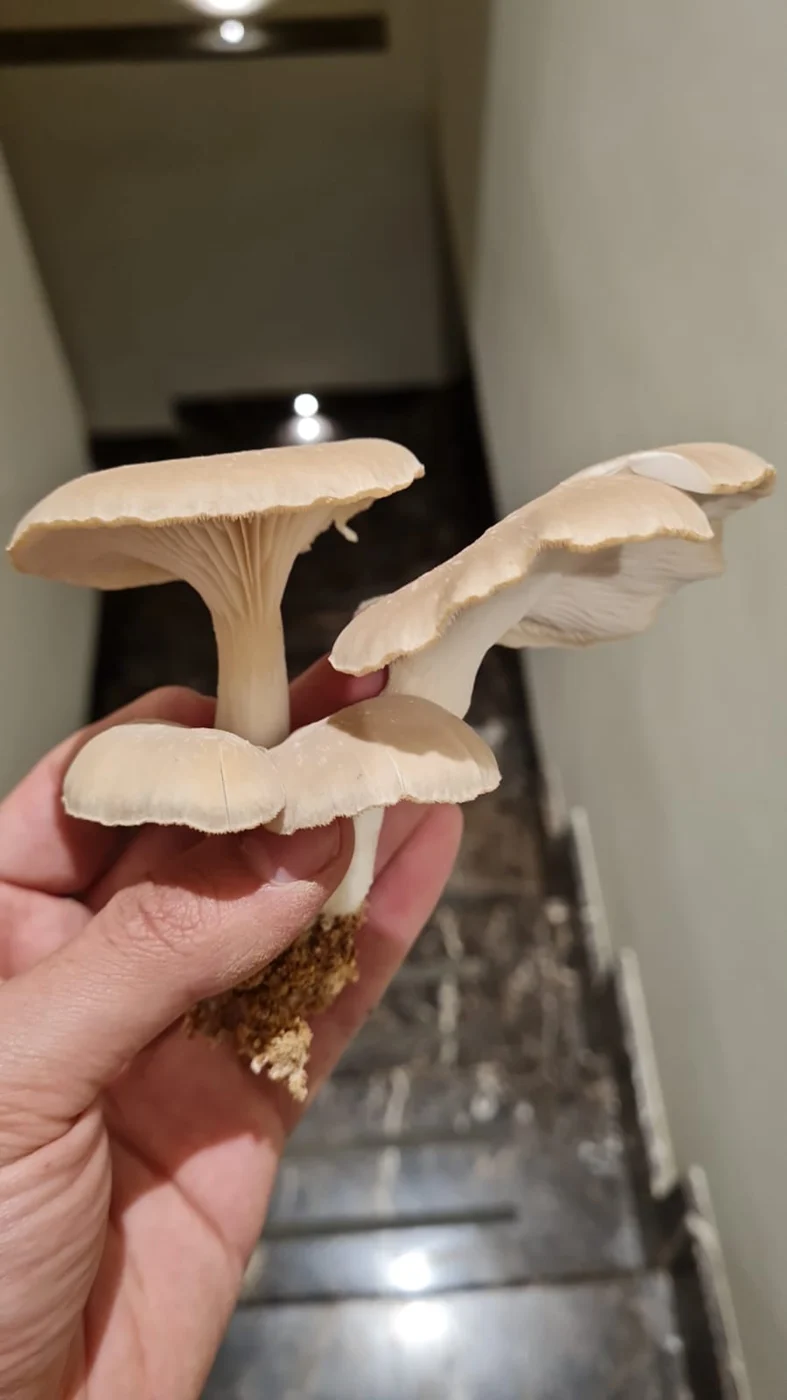
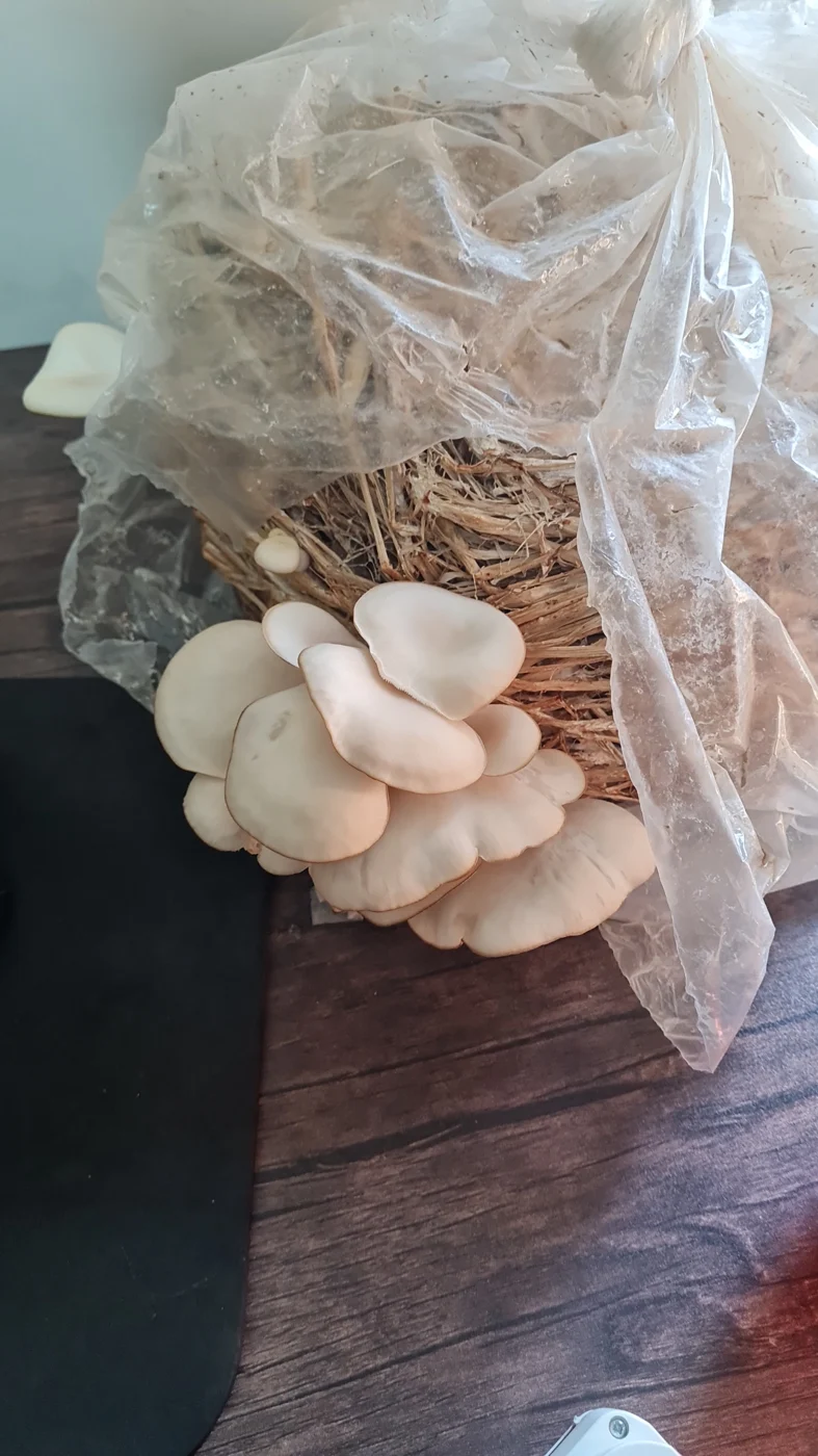
Oyster mushrooms grow in hanging bags of straw substrate. Incubation, pinning, fruiting, and harvest provide a conceptual structure for observing the cultivation process.

In the margin

Photographs preserve visible changes. Missing observations and uncertainty remain part of interpreting the run.

12
SMART MUSHROOM HUB

A restart ≠ a recovery.

The supplied hardware workbench photograph, illustrating the interconnected equipment discussed in the reliability notes.
1

This photograph provides hardware context only. It is not evidence of the sensor failure described on the facing page.

Connected equipment, shared points of failure

Hardware reference photograph · not an incident capture

Missing observations are observations about the system.

CLICK THE PHOTO TO LOOK CLOSER13
07 / WHAT WENT WRONG

Leave room for the inconvenient parts

Keep the crossed-out ideas.

By 31 August 2026, the investigation found that sensor records had stopped after 24 August. Repeated SCD41 initialization failures appeared to terminate the shared publisher, interrupting the other sensors too.

What that taught us

Isolate failures. One unavailable sensor should not silence the rest of the observations.

Check the outcome. A running process is not proof of recovery. Restarting the camera timer also once caused an unexpected extra capture.

Keep uncertainty visible. Missing records and unfinished integrations belong beside the successful parts of the build.

These are historical notes, not current service status.

14

CRAFTY AMIGO / FIRST DRAFT

Initial design

Initial three-dimensional PVC tent design created in Crafty Amigo

The first calculation

PVC cut list

QuantityPart
42T joints
426-inch pieces
1418-inch pieces
412-inch pieces
228-inch pieces
416.75-inch pieces

THE JOURNEY /

Photos & dates

EXPLORE THE PROJECT

A link still to come.

The public project link is not available here yet.

You can explore the experiment, hardware, and system documentation on this site.

Read the documentation